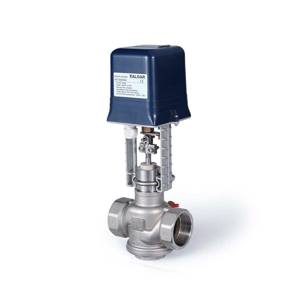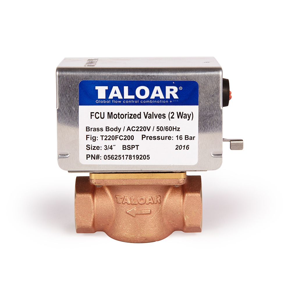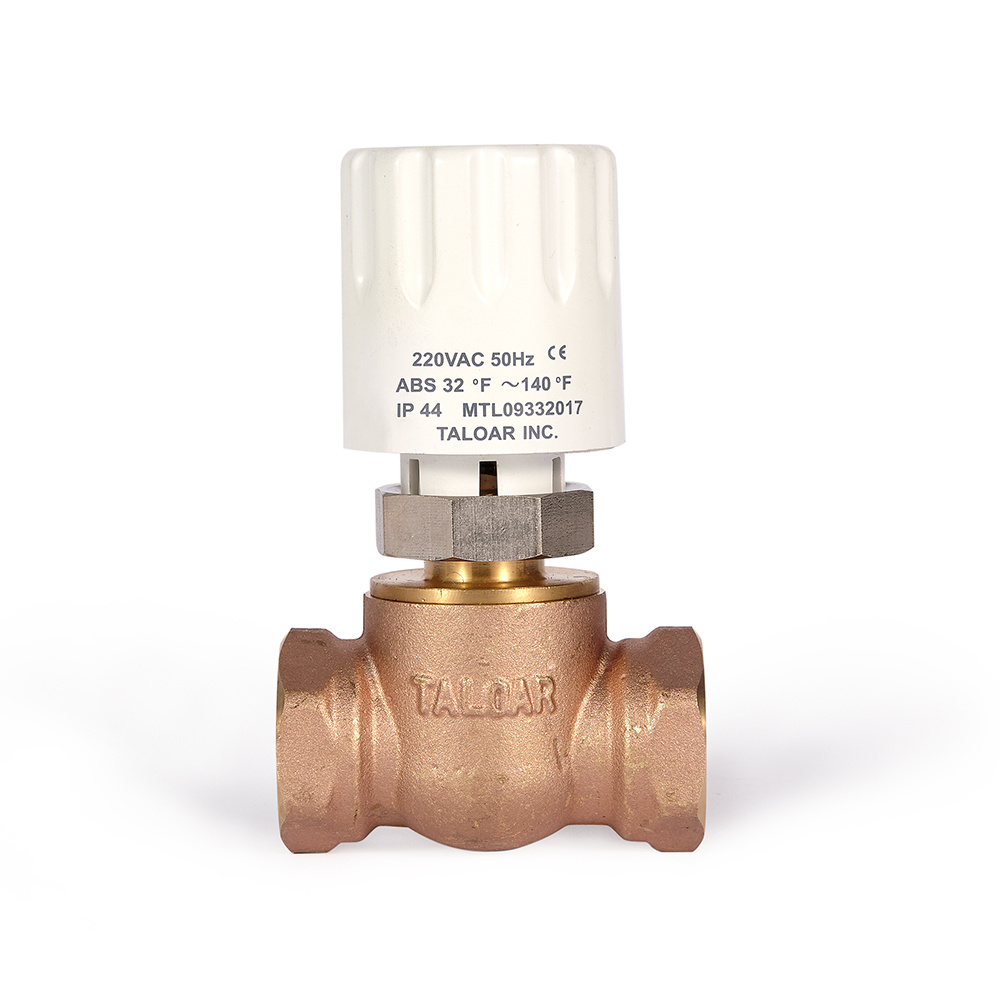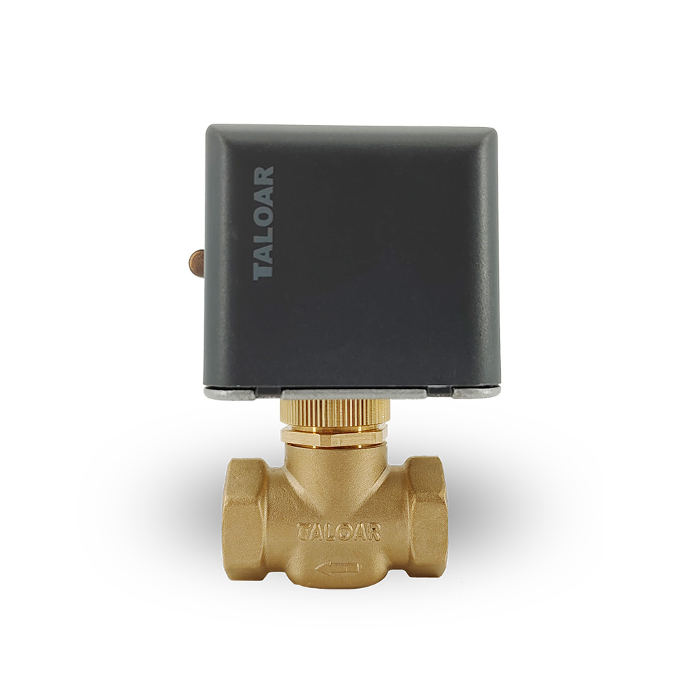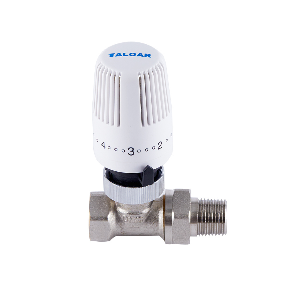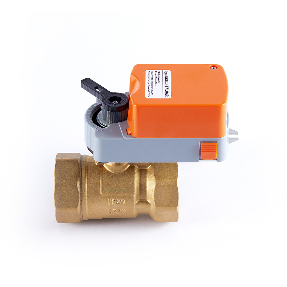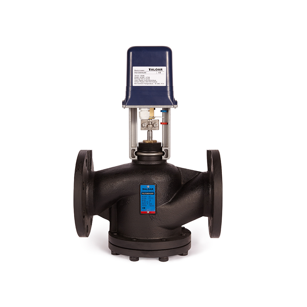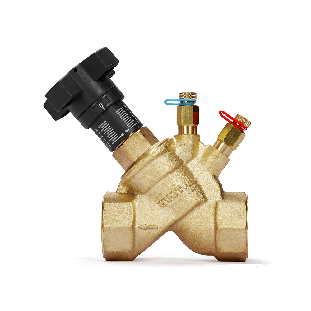

Stainless-steel threaded motorized control valves of UL330/350 and AF550/572 series apply to HVAC and building automation systems. Once the motorized control valves receive signals transmitted by computers or other devices, they can then adjust temperature, pressure and control system parameters such as flow rate and liquid level. The valves are mainly used to convey mediums such as cold water, hot water, and ethylene glycol solution.


Product Features
Adopt the AC synchronous hysteresis clutch motor. When the limited position is reached, the hysteresis clutch disengages the motor's output shaft from the transmission part to protect the motor.
High-precision control offers precise actions.
Low power consumption and low noise.
Have the self-adaptive valve travel function.
Multiple signal controls: Increment/floating-point signal, voltage 0 - 10 V, current 4 - 20 mA.
ABS shell and cast-aluminum bracket with the advantages of small size and light weight.
Easy installation and maintenance.
Technical Parameters
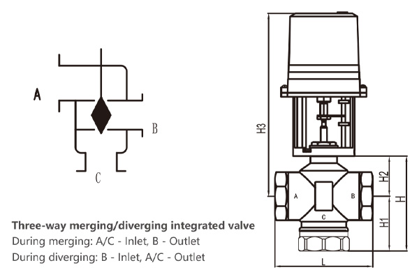
Valve Type: Two-way valve,three-way valve
Material: Shell:stainless steel; disc/stem: stainless steel;sealing: PTFE
Working Pressure: 2.5 Mpa
Medium: Cold water, hot water, vapor, and the aqueous solution of ethylene glycol (concentration within 50%)
Medium Temperature: 0°C ~ 110°C/0°C ~ 150°C with a heat dissipation device
Flow Characteristic: Equal percent curve/equivalent linear
Leakage Volume: Below 0.02% of Kv Value
End Type: BSPT or NPT tnreaded
Actuator Parameters
| ltem | Performance parameters | |
| Model | UL series (incremental control model) | AF series (proportional adjustment model) |
| Power Supply | AC 24 VAC/220 VAC±10%,50 Hz/60 Hz | |
| Force | 500N,1000N | |
| Power Consumption | <5.5VA | |
| Operating Speed | 0.20mm/s(50Hz) | |
| Control Signal | Increment/floating-point signal | 0~10VDC or 4~20 mA |
| Working Temperature | -10°C ~ 50°C (50°F ~ 120°F) | |
| Humidity | 10%~90%RH,no condensation | |
| Maximum Travel | 25 mm | |
| Actuator Weighi | 2.4Lbs/1.1 kg; 2.7Lbs//1.2 kg | |
| Materials Of Main Parts | Fire-retardant ABS plastic shell and die-cast aluminum bracket | |
| Waterproof Rating | IP54 | |
| Power-off State | Stay in the current position | |
| Valve Opening Before Delivery | Middle position | |
| Manual Function | Have manual operation | |
| Valve Opening Indication | Have valve opening indication | |
| Insulation Resistance | Resistance between the power supply terminal and the shell:≥50 MΩ;that between the input terminal and the shell:≥20 MΩ. | |
| Dielectric Strength | Dielectric strength between the power supply terminal and the shell:500 V,50 Hz for AC24V equipment; 1,500 V,50 Hz for AC220 equipment;that between the input terminal and the shell:500 V,50 Hz |
|