Safe partition and low head loss
Light weight
Reliable sealing performance
Compact structure design, saving installation space
Easy maintenance, and vertical or horizontal installation

Safe partition and low head loss
Light weight
Reliable sealing performance
Compact structure design, saving installation space
Easy maintenance, and vertical or horizontal installation

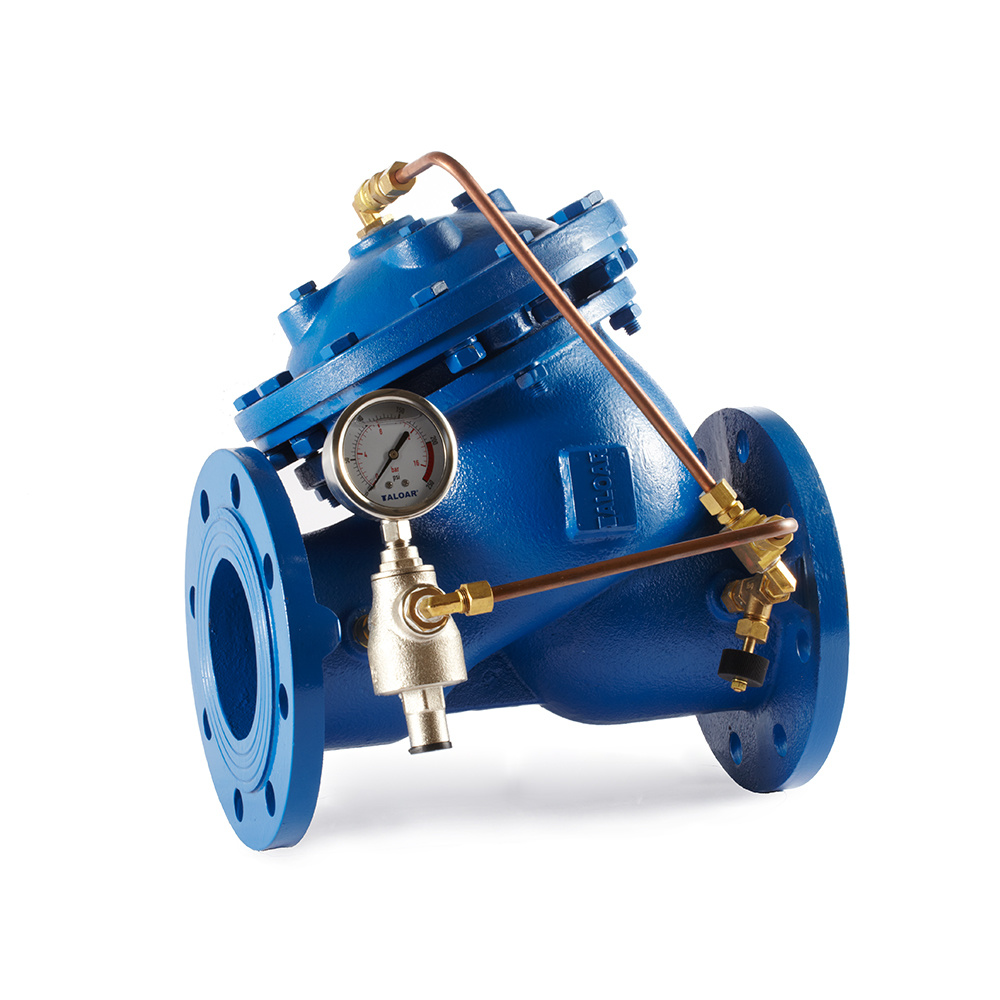
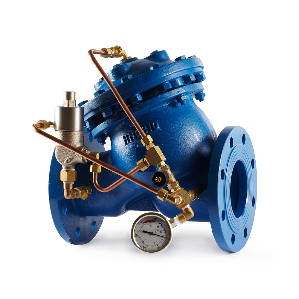
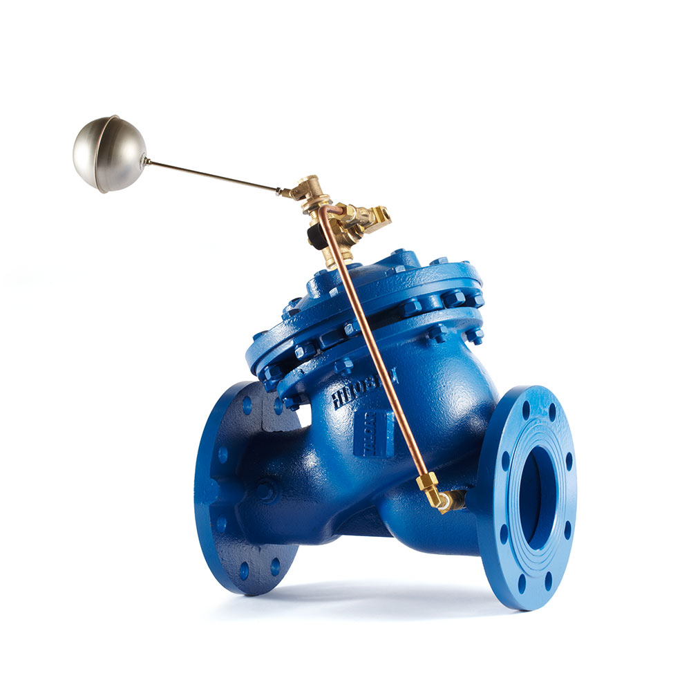
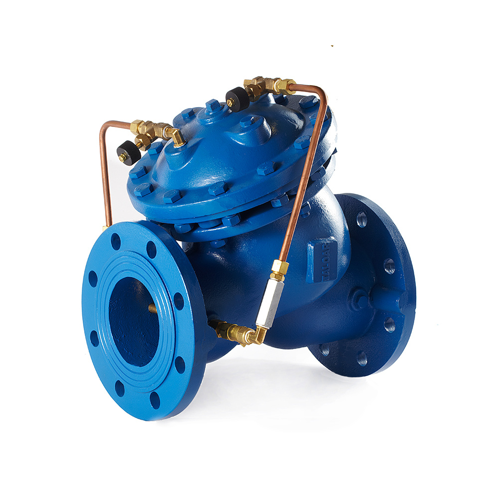
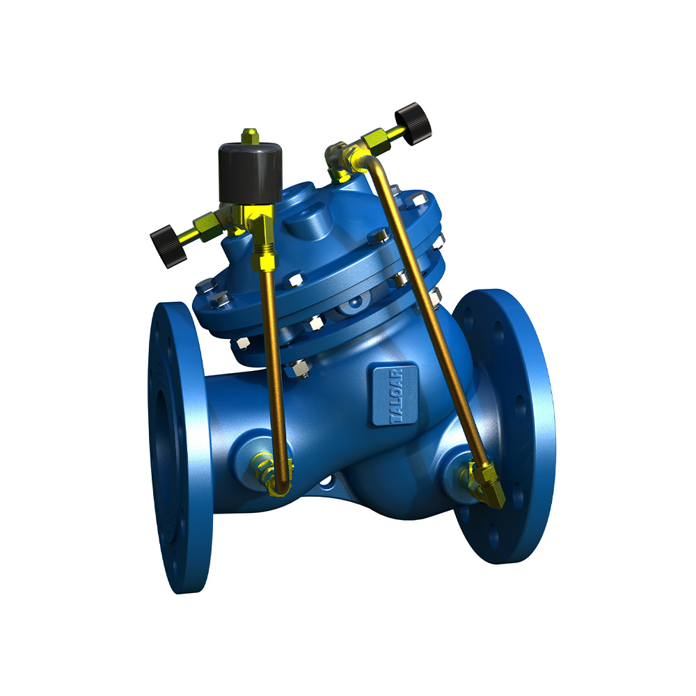
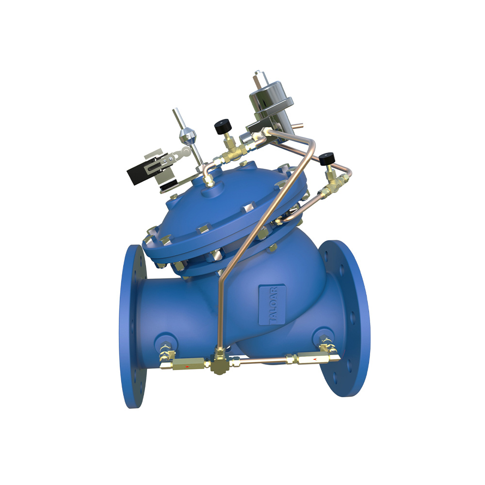
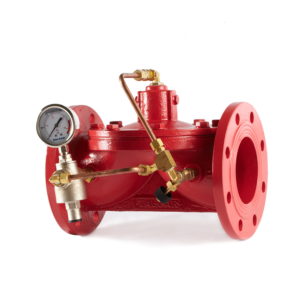
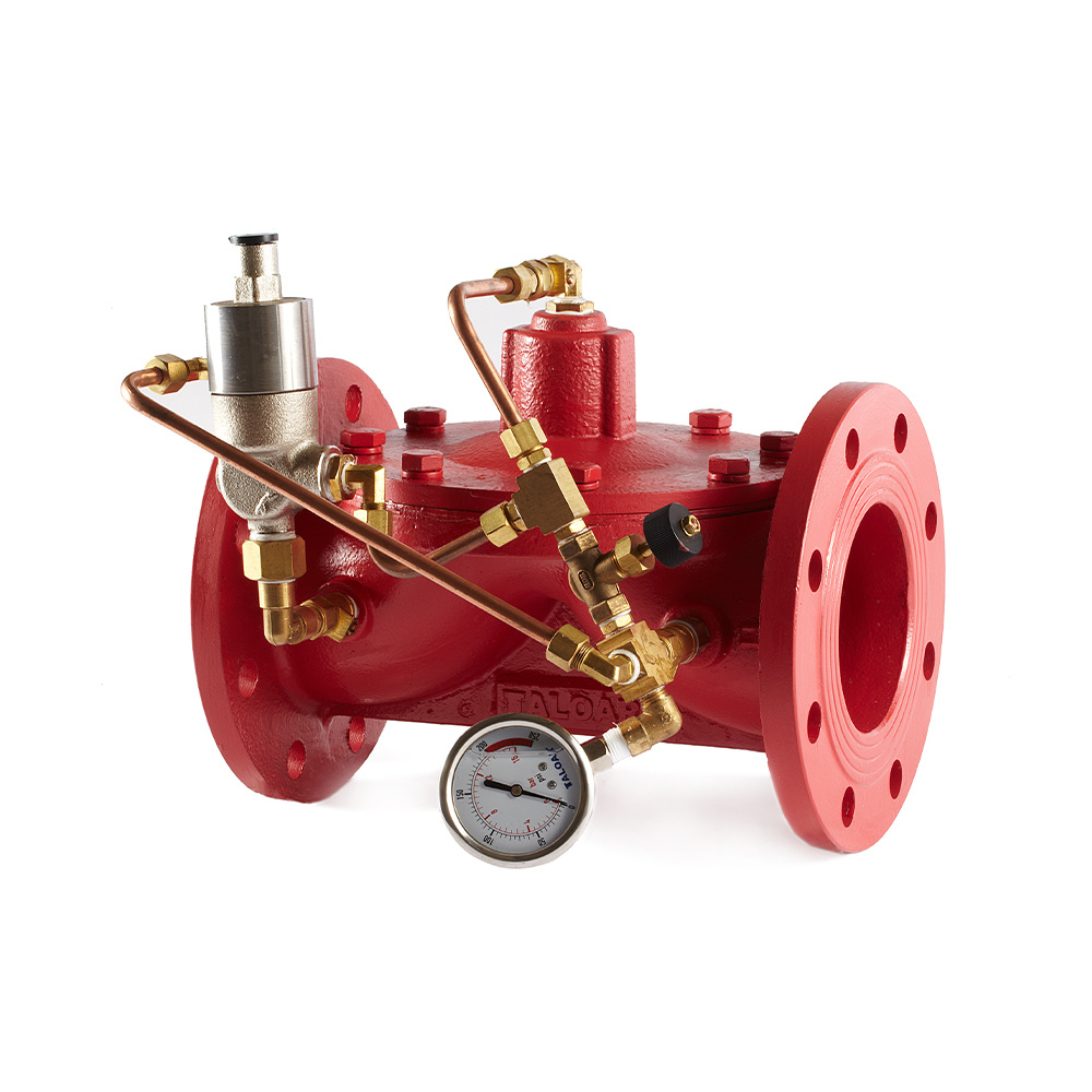
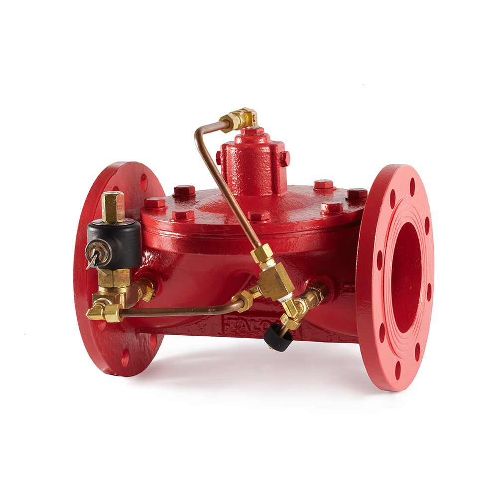
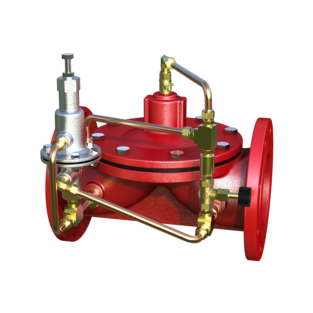
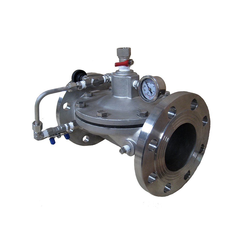
500X backflow prevention device consists of a basic valve with two-stage non-return device and an external drainer, where both ends of the drainer′s guide piping are connected to the inlet and outlet of the basic valve respectively. When inlet pressure is greater than the outlet pressure, the drainer will automatically close. When the outlet pressure is greater than inlet pressure, the drainer will automatically open to drain the medium in the middle chamber of the basic valve to form an air partition to ensure the water supply safety.
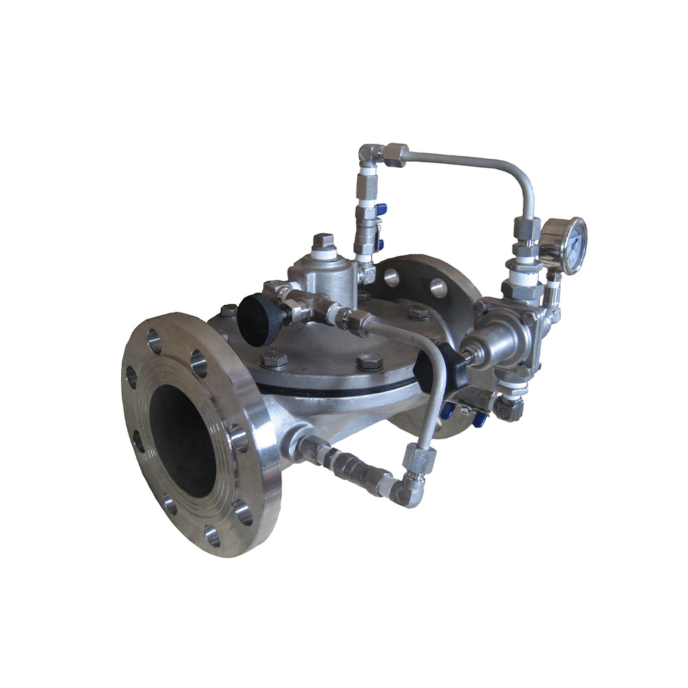
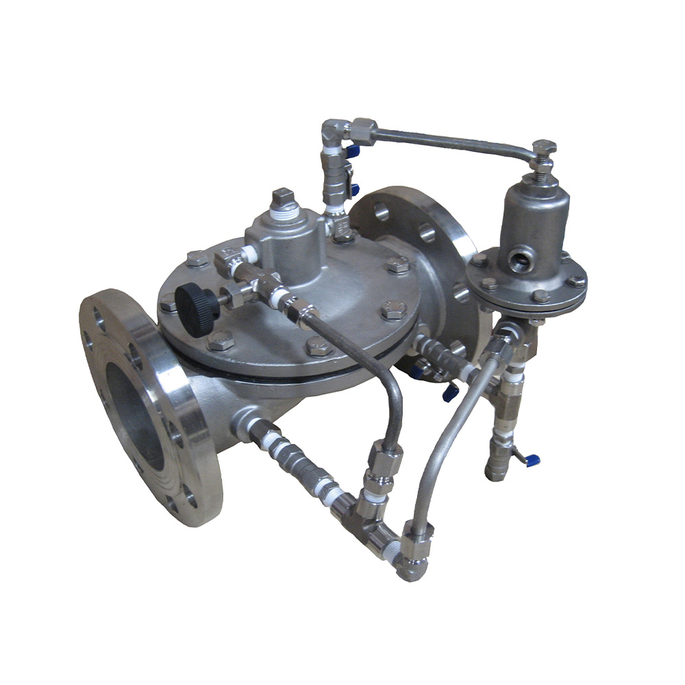
Body/Bonnet: Ductile Iron/Stainless Steel
Disc: Stainless Steel
Seat: Stainless Steel
Spring: Stainless Steel
Drainer: Stainless Steel
Seal Ring: NBR
175PSI/235PSI/350PSI
10Bar/16Bar/25Bar
ANSI / BSEN / DIN
0°C~100°C normal temperature water
≤0.3 Bar
Valve figure number/size/pressure grade/connecting end type/other optional accessories
Note: In valve installation, it is strongly suggested that sufficient space should be left for easy maintenance in the future. A strainer shall be mounted in front of the valve to prevent foreign matters from blocking the valve.
① Body
② Front Seat
③ Valve Shaft
④ Front Disc
⑤ Main Spring
⑥ Rear Seat
⑦ Rear Disc
⑧ Guide Bush
⑨ Aux Spring
⑩ Drainer

| Size(mm) | 50 | 65 | 80 | 100 | 125 | 150 | 200 | 250 | 300 |
| L(mm) | 190 | 210 | 225 | 250 | 300 | 340 | 400 | 460 | 540 |
| B(mm) | 165 | 185 | 200 | 215 | 250 | 280 | 340 | 405 | 460 |
| H(mm) | 190 | 205 | 225 | 252 | 290 | 318 | 370 | 500 | 560 |
To facilitate installation and maintenance and ensure the normal use of the backflow prevention device, the control valve and the strainer should be installed before the backflow prevention device and the flexible connector, and the control valve should be installed after the backflow prevention device.
At the drain outlet of the backflow prevention device, a drain pipe should be installed about ≥100 mm above the water collecting well. No valve should be installed in the drain pipeline to block the flow of the medium.The drainage diameter of the water collecting well should ensure smooth drainage.
To facilitate routine inspection and maintenance, the low-resistance backflow prevention device should not be installed in the outdoor well. It is recommended to install the backflow prevention device indoor, with sufficient reserved space. Generally the spacing to the lower edge should be ≥300 mm for convenient installation and maintenance.
The low-resistance backflow prevention device can be installed horizontally or vertically and the flow direction of medium in pipelines should be in line with the direction indicated by the arrow marked on the basic valve body.
Before installation, the pipe network must be thoroughly cleaned. Besides, the strainer screen of the strainer must be cleaned regularly.
Copyright © TALOAR All Rights Reserved